Home| Project Details | Group Members | Weekly Progress | UML Diagrams | Code
Project Details
I. Project Overview
This project addresses the challenge of producing a unified visual output from multiple projectors by developing a software-driven image composition system. The system combines two projected images into a single coherent display while minimizing visible boundaries, luminance variation, and color imbalance across overlapping regions.
The implementation is based on Python and the OpenCV framework. Computational image-processing techniques such as luminance normalization, transparency-based blending, and spatial intensity control are applied to correct projection inconsistencies caused by illumination differences and surface variation.
II. Motivation and Problem Definition
Multi-projector systems commonly exhibit discontinuities in overlapping regions. Since projectors emit light, the overlapping region where two projectors meet receives double the light intensity Left + Right, resulting in a visible "bright band" or seam.- The Artifacts : Visible seams, uneven brightness, and color distortion.
- The Solution : This project proposes an automated, software-based alternative that performs alignment and blending algorithmically, eliminating the need for expensive hardware blend units.
III. System Capabilities
The system supports:- Automated Projection Blending : Merges left and right images based on a configurable overlap width.
- Luminance Normalization : Corrects for the non-linear brightness output of projectors using Gamma correction.
- Real-Time Processing : Capable of processing image inputs efficiently using NumPy matrix operations.
- Modular Architecture : Separates configuration, logic, and display for maintainability.
IV. Algorithms and Theoretical Framework
The system operates on a shared projection surface illuminated by synchronized projectors. To achieve a seamless blend, we implement two core mathematical adjustments: Alpha Blending and Gamma Correction
A. Alpha Blending (Transparency Control)
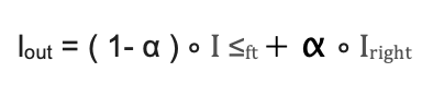
Alpha blending merges two visual layers based on a transparency coefficient Alpha. We generate a gradient mask where the transparency of the left image fades from 1.0 to 0.0, and the right image fades from 0.0 to 1.0.
Linear Blending Formula:
B. Gamma Correction (Luminance Normalization)
Standard linear blending fails because projectors are non-linear devices. A pixel value of 50% (128) does not result in 50% light output; due to the projector's gamma (approx. 2.2) it results in only ~22% light output. This causes the blended region to appear darker than the rest of the image (a "dark band").
To correct this, we apply an Inverse Gamma function to the blend mask before applying it to the image. This "boosts" the pixel values in the overlap region so that the final optical output is linear.
Gamma Correction Formula:
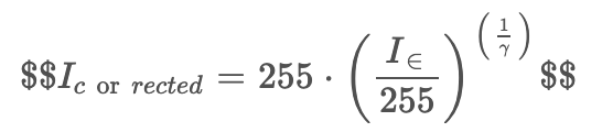
By setting gamma to match the projector (typically 2.2), we ensure that: Software Correction Projection Gamma = Linear Output
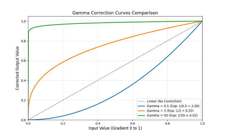
Figure 1. The relationship between input pixel intensity and corrected output. The orange line shows the software correction (gamma=3) boosting values to counteract the projector's drop (gamma ~2.2). The dashed grey line represents a linear response (no correction), while the blue and green lines represent under-correction (gamma=0.5) and over-correction (gamma=50) respectively.
V. Experimental Validation: Gamma Analysis
To validate the necessity of Gamma Correction and verify our software's behavior, we performed a comparative analysis. First, we generated a computational plot of the blending mechanics, followed by physical projection tests using three distinct Gamma values to observe the real-world impact on luminance uniformity.
A. Blending Mechanics and Theoretical Boost
To visualize how the inverse gamma correction modifies the standard linear fade, we generated a spatial intensity plot of the overlap region (Figure 1).
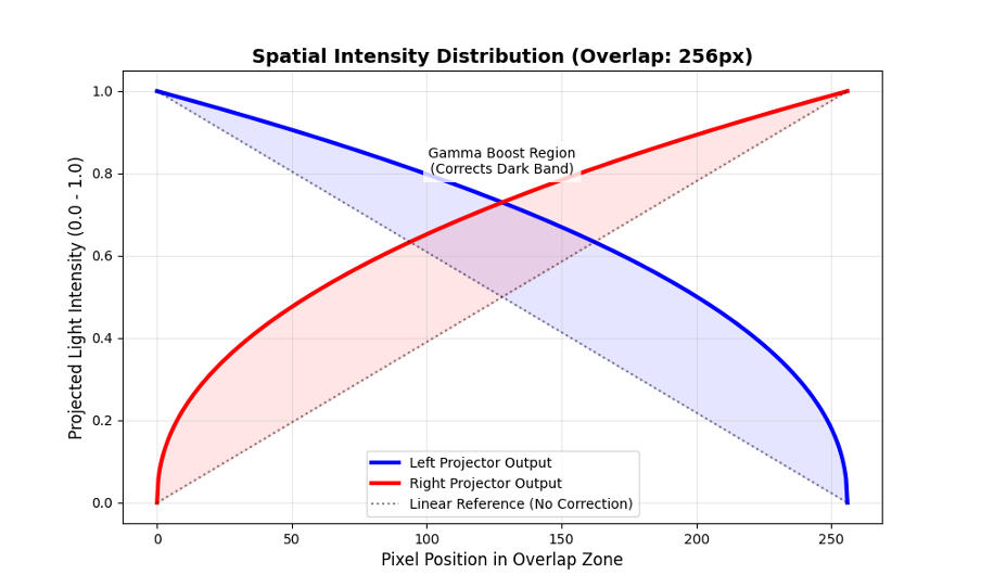
Figure 2. Spatial intensity plot of the overlap region. The dashed lines represent a standard linear fade, which results in insufficient light output. The solid blue and red curves show the gamma-corrected output (boosting the mid-tones) applied by our software to compensate for projector non-linearity.
As illustrated in Figure 2, the solid curves bow upward across the overlap zone. This represents the mathematical "boost" applied to the pixel values. By increasing the intensity of the mid-tones before they reach the projector, we counteract the projector's physical tendency to dim those mid-tones, theoretically resulting in a linear, uniform light output.
B. Physical Projection Results
We tested this theory physically by projecting a test image and varying the gamma parameter in the configuration.
Case 1: Under-Correction (gamma = 0.5)
Applying a gamma value below 1.0 results in a curve that bows downward, worsening the natural dimming effect of the projectors.
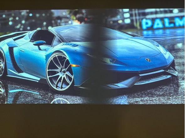
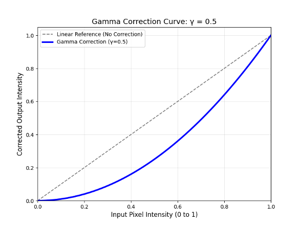
Figure 3. Physical projection result using gamma = 0.5. A distinct "dark band" is visible in the center overlap region due to under-correction of luminance.
As seen in Figure 3, the overlap region is significantly darker than the non-overlapped areas. The software darkened the mid-tones too quickly, compounding the projector's natural light loss. This confirms that a concave (downward-bowing) blending curve is unsuitable for uniform projection blending.
Case 2: Optimal Compensation (gamma = 3.0)
Applying a gamma value near the industry standard for display devices (typically between 2.2 and 3.0) provides the necessary upward boost to the mid-tones.
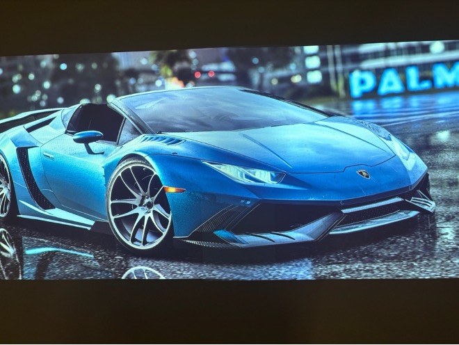
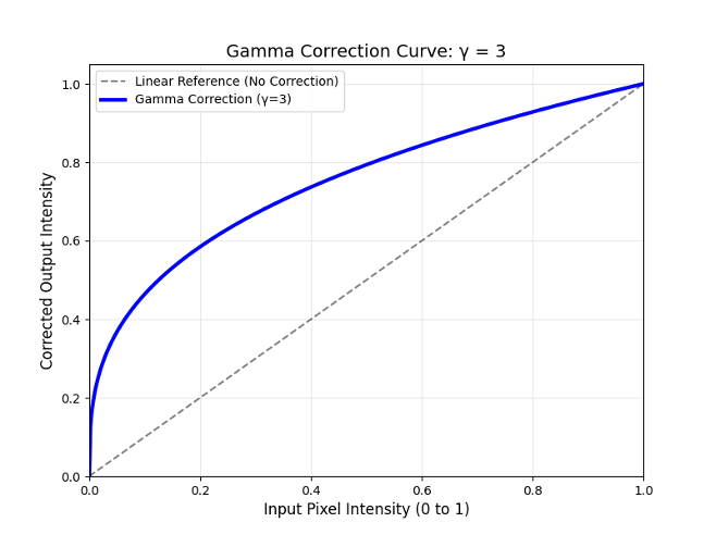
Figure 4. Physical projection result using gamma = 3.0. The blend is seamless, with uniform brightness achieved across the entire overlap zone.
Figure 4 demonstrates a successful blend. The luminance boost applied by the software effectively cancelled out the projector's physical gamma curve. The sum of the light intensities from both projectors produces a uniform brightness level, rendering the seam invisible to the naked eye.
Case 3: Over-Correction (gamma = 50.0)
Applying an extreme gamma value tests the limits of the algorithm. Mathematically, this creates a curve that jumps almost instantly from black to maximum brightness.
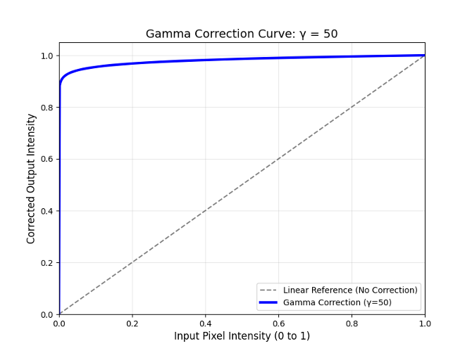
Figure 5. Physical projection result using gamma = 50.0. The gradient is destroyed, resulting in a hard, bright edge instead of a smooth transition.
As shown in Figure 5, extreme over-correction destroys the gradient necessary for a smooth transition. The overlap area becomes a uniform bright band with hard edges. This validates that while a luminance boost is necessary, the correction curve must be graduated to match the projector's response characteristics; an excessively steep curve eliminates the blending effect entirely.
VI. Software Architecture
The system is structured into two primary classes to ensure modularity and separation of concerns.
1. ConfigReader: Manages external configuration parameters (JSON) such as gamma values, screen side, and overlap width.
2. Main_Alpha_Blendert: Performs the core mathematical operations. It generates the NumPy masks, applies the gamma power functions, and merges the alpha channels.
VII. Functional Requirements
- Input: The system accepts standard image formats (JPG, PNG)
- Configuration: Users must be able to adjust the gamma value and the image size through the config.json file.
- Output: The system must generate left and right specific images that, when projected physically, align to form a single continuous image.
VIII. Development Tools
- Python & OpenCV: Used for matrix manipulation and image rendering.
- NumPy: Essential for performing the gamma power function on millions of pixels simultaneously for real-time performance.
- Doxygen: Used to generate automated technical documentation.
Updated by WONGKAI Briana Monika Luckyta 4 months ago · 10 revisions